Search Knowledge Base by Keyword
-
Case Studies
- A Sugary Sweet Lifting Solution for Peeps & Company Retail Store
- Bayside Harley’s Product Showcase and PFlow Bring in the Riders
- Books Arrive in Underground Archive with the Help of a PFlow Conveyor
- Creative Design Highlights Vertical Conveyor at Laminated Glass Plant
- Custom Designed Hydraulic VRCs Help Maximize Space at Tyson Foods
- Custom Designed PFlow F Series Assists with Funeral Services
- Custom PFlow Lift Helps Create 9,600 SF of Storage within Existing Building
- Everything is Bigger In Texas – Including the PFlow M Series VRC!
- For Moving Fragile Cargo, Boeing Called PFlow Industries
- FuelCell Energy Loads Components with the Help of PFlow Material Lifts
- Georgia Pacific Moves Finished Product with the PFlow M Series
- Global Logistics Leader Doubles Productivity with PFlow Lifts
- Gravity Makes the Wine, PFlow Vertical Lift Takes Care of the Rest
- Historic Pritzlaff Building Repurposed Into Popular Event Venue with Assist from PFlow Hydraulic VRCs
- Liberated By Upward Mobility
- Manufacturing Plant Replaces 10-ton, 200′ Hoist with PFlow Vertical Lift
- Merged Controls of PFlow Lift and Laundry Cart Washer Regulate the Flow of the Entire System
- Milwaukee Waterfront Deli and PFlow Deliver
- Moving at the Speed of Fashion
- Moving-Floor Assembly Line Streamlines Implement Production
- PFlow and Parking Vault are Solving Major Parking Needs
- PFlow Automated System Provides Continuous 2-Way Pallet Flow
- PFlow Corners the Market for 'Big,' Heavy-Duty Material Lifts
- PFlow Designs Lift for Underground Parking at a Lake Tahoe Home
- PFlow F Series Helps Retailer Utilize Difficult-to-Access Space
- PFlow Galvanizing Provides a Protective Coat for Juice Plant Lift
- PFlow Heliport Lift Helps Offshore Oil Platform
- PFlow Helps Repurpose Restaurant into Government Service Facility
- PFlow Hydraulically Powers the Upward Expansion at Alcom Electronicos Reynosa Facility
- PFlow Lift Integrates Perfectly with 10-Story Power Plant Tower
- PFlow Moving Concourse Helps 'Big Bertha' March Into College Stadium
- PFlow Navigates Uncharted Territory with Vertical Lift at Naval Drydock
- PFlow Pallet Elevator is the Vertical Lift Solution for Nutrilite Warehouse
- PFlow Provides Steady Travel for Lockheed Martin Missile Plant
- PFlow Retrofits 2 Lifts in Single Shaft to Keep Hospital Supplies Moving
- PFlow Screw Lift Provides a Safe and Controlled Movement of Satellites
- PFlow System is an Integral Part of the Paper Production Line
- PFlow VRC Keeps the Pipeline Full for Large Pharmaceutical Distributor
- PFlow VRCs Help Keep the Beer Crisp and Chilled at NFL Stadium
- PFlow VRCs Installed in Concrete Shaft Ways of Seattle Tunnel Project
- PFlow VRCs Provide Vertical Logistics at High Rise Audi Dealership
- Stage Lifts Spirits – and Nascar Vehicle
- Tower Above the Competition with a PFlow Vehicle Display System
- Unique Lift System Enables Installation and Servicing of Telescope Mirrors
- Show all articles ( 29 ) Collapse Articles
-
Preventive Maintenance
- 21 Series Hydraulic Lift - Preventive Maintenance Checklist
- B Series Box Lift - Preventive Maintenance Checklist
- D Series Hydraulic Lift - Preventive Maintenance Checklist
- DB Series Package Handling Lift - Preventive Maintenance Checklist
- F Series 4-Post Mechanical Lift - Preventive Maintenance List
- M and MQ Series Mechanical Lifts - Preventive Maintenance Checklist
-
Service Bulletins
-
Installation Manuals
- 21 Series - Hydraulic VRC - 2-Post Cantilever - Installation Manual
- 21 Series - Hydraulic VRC - 2-Post Straddle - Installation Manual
- B Series - Box Lift - Owner's, Installation, and Maintenance Manual
- D Series - Hydraulic VRC - Installation Manual
- DB Series - Package Handling Lift - Owner's, Installation, and Maintenance Manual
- F Series - Mechanical VRC - 4-Post Installation Manual
- M Series - Mechanical VRC - 2-Post Cantilever - Installation Manual
- M Series - Mechanical VRC- 2-Post Straddle- Installation Manual
-
Owner's Product Manuals
- 21 Series - Hydraulic VRC - Owner's Manual
- B Series - Box Lift - Owner's, Installation, and Maintenance Manual
- D Series - Hydraulic VRC - Owner's Manual
- DB Series - Package Handling Lift - Owner's, Installation, and Maintenance Manual
- F Series - Mechanical VRC - Owner's Manual with Eurodrive
- F Series - Mechanical VRC - Owner's Manual with NORD Motordrive
- M Series - Mechanical VRC - Owner's Manual with Eurodrive
- M Series -Mechanical VRC - Owner's Manual with Nord Motordrive
-
Dimensional Schematics
- 21 Series CSI Spec - No Quick Connect
- 21 Series CSI Spec - Quick Connect
- 21 Series Hydraulic Lift - Cantilever Style - Dimensional Schematic
- 21 Series Hydraulic Lift - Straddle Style - Dimensional Schematic
- 21 Series, Cantilever, CAD Drawing
- 21 Series, Straddle, CAD Drawing
- B Series Box Lift - Dimensional Schematic
- Bi-Panel Swing Gate Dimensions
- Bi-Panel Vertical Gate Dimensions
- D Series CAD Drawing
- D Series CSI Spec - No Quick Connect
- D Series CSI Spec - Quick Connect
- D Series Hydraulic Lift- Dimensions Schematic
- DB Series CAD Drawing
- DB1 Series Package Handling Lift - Dimensional Schematic
- DB2 Series Package Handling Lift - Dimensional Schematic
- F Series 4-Post Mechanical Lift - Dimensions Schematic
- F Series CAD Drawing
- F Series CSI Spec
- M Series 2-Post Mechanical Lift - Cantilever Style - Dimensions Schematic
- M Series 2-Post Mechanical Lift - Straddle Style - Dimensional Schematic
- M Series CSI Spec
- M Series, Cantilever, CAD Drawing
- M Series, Straddle, CAD Drawing
- Single Panel Vertical Gate Dimensions
- Single Sliding Gate Dimension
- Single Swing Gate Dimensions
- Show all articles ( 12 ) Collapse Articles
-
Applications
-
Videos
-
Gate Installation Instructions
- 15709-0005 - Gate Installation - Sliding - Swing - Bi-Parting
- 15709-0014 - Gate Installation - Bi-Panel Vertical Acting
- 15709-0120 - Gate Installation - Floor Level Swing with Sliding Latch
- 15709-0126 - Gate Installation - Floor Level Bi-Swing with Sliding Latch
- 15709-0133 - Gate Installation - Motorized Single Vertical Acting
- 15709-0143 - Gate Installation - Motorized Bi-Panel Vertical Acting
- 15709-0156 - Gate Installation - Single Vertical Acting
- 15709-0157 - Gate Installation - Carriage Mounted Single Vertical Acting
-
Safety Data Sheets
- 15713-0001 - SDS, Lubriplate 930 AAA
- 15713-0002 - SDS, Mobil SHC 630, Standard Synthetic Oil
- 15713-0003 - SDS, MobilGear 600 XP 220, Standard Base Oil
- 15713-0004 - SDS, Shell Omala S4 GX 220, Gear Lubricant
- 15713-0007 - SDS, Paint, Enamel - PFlow Blue, Aerosol
- 15713-0008 - SDS, Exxon MobilGrease XHP 222 Special
- 15713-0011 - SDS, Paint, Fast Dry Acrylic Enamel, PFlow Blue
- 15713-0012 - SDS, Paint, Universal Primer, PFlow Primer II
- 15713-0014 - SDS, Hydraulic, Biodegradable, Clarion AW Oil 32
- 15713-0015 - SDS, Weld-Aid Brite Zinc B-100, Aerosol
- 15713-0018 - SDS, Shell Omala S2 G 220, Gear Lubricant
- 15713-0021 - SDS, Fast Cure Epoxy, Macropoxy 646 (Part A) Mill White
- 15713-0022 - SDS, Dow Corning Oil, Molykote L-1468FG, Synthetic Freezer Chain Oil
- 15713-0023 - SDS, Mobil SHC CIBUS 220, Synthetic Oil
- 15713-0026 - SDS, Eureka Fluid Film Aerosol, Corrosion Inhibitor
- 15713-0028 - SDS, Benz Oil DEXRON III, ATF Hydraulic Fluid
- 15713-0031 - SDS, Shell Omala S4 GX 150, Gear Oil
- 15713-0035 - SDS, Starfire Multi-Purpose ATF Dexron III/Mercon
- 15713-0036 - SDS, Clarion Food Grade Machinery AW 32, Hydraulic Oil
- 15713-0038 - SDS, Paint, Safety Yellow, Aerosol
- 15713-0039 - SDS, Paint, Safety Yellow, Enamel
- 15713-0042 - SDS, Roll-on Paint, PFlow Blue
- 15713-0043 - SDS, Mobil SHC Gear 220 Synthetic Gear Lubricant
- 15713-0044 - SDS, LPS Cold Galvanize BrightCoat Aerosol
- 15713-0045 - SDS, CRC Dry Graphic Lubricant
- 15713-0046 - SDS, Duraspar 130 Gray Primer
- Corothane Exterior Epoxy - Safety Data Sheet
- Corothane Exterior Epoxy Hardener - Safety Data Sheet
- Show all articles ( 13 ) Collapse Articles
Moving-Floor Assembly Line Streamlines Implement Production
Located in the very heart of Canada’s Saskatchewan farm country in the small town of St. Brieux, is Bourgault Industries (Bourgault), which, since 1974, has designed, manufactured and distributed farm equipment for seed planting and tillage.
Recently, the company added 184,000 square feet of production area to one of its several manufacturing facilities in St. Brieux.
The main goal of the expansion was to consolidate its tillage product line into one manufacturing facility, and increase efficiency by reducing the handling and transporting of parts.
Project Overview
Saskatchewan, Canada
Farm Equipment Manufacturer
- Moving-Floor System
- Carries loads up to 200,000 lbs
- 4’ Vertical Rise
- 2 Levels of Vertical Rise
- 20 FPM Travel Speed
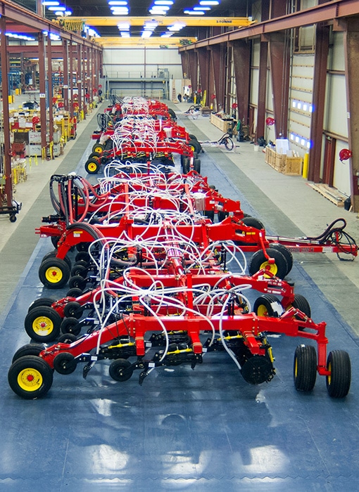
Like many farm equipment manufacturers, Bourgault’s equipment is not only built to be heavy-duty and durable, but very large in size. Its tillage equipment can vary in size up to 125 sq. ft. in width, weighing in at more than 75,000 lbs. Assembly-line systems, conventionally employed for large equipment – such as drag-line conveyors that move products between stations or cells where specific tasks are performed – lose efficiency, productivity and safety when dealing with assembled-equipment requirements of such large size.
The manufacturing of Bourgault’s tillage equipment is segmented into two different sections. The framework is welded together, powder coated, and then hydraulic cylinders are installed in one section of the plant. This assembly is then moved to another section of the plant where ground openers, fertilizer and seed dispensing systems, and other options specified by customers, are assembled and tested. It was in this assembly stage where Bourgault engineers confronted their biggest challenge in designing a more efficient and streamlined system to integrate into its newly-expanded facility.
Engineering an Ultra-Large-Scale Moving-Floor Assembly Line
“We conducted considerable research on different systems for assembly of our tillage equipment,” said David Konopacki, lead engineer with Bourgault. “We consulted with a number of system manufactures, but none could provide a solution to meet our needs, because the sheer size and weight of our tillage equipment exceeded their systems’ capabilities.”
After assessing many different options, Bourgault’s internal engineering team, led by Konopacki, determined that a moving-floor assembly line would deliver the best throughput volumes and cost efficiencies for the company’s needs. The idea was to have the moving floor not only support the tillage equipment during assembly, but to also have it support the kitting systems and parts to be assembled, as well as the workers doing the assembly. By the time the tillage equipment reached the end of the assembly line, it would be completely assembled and tested, and ready to be discharged from the moving assembly floor, and destined for warehousing or shipping.
To facilitate bringing this design concept to fruition, Bourgault brought in PFlow Industries to co-engineer and build the moving-floor assembly system. Working in tandem, the PFlow and Bourgault engineering teams came up with a unique ultra-large-scale moving-floor assembly system. The design utilizes a string of 25’ x 10’ wheeled carts, with a working surface of steel plates to support the tillage equipment and the workers performing the assembly functions. These 37 cart segments were designed to be queued end-to-end to form a continuous 370’ L x 25’ W floor, which would be pushed along on rails by hydraulic cylinders. As the carts reached the end of the line, the completed tillage equipment would be rolled off from the assembly system. The carts would then be lowered, and transported underneath the assembly system back to the front of the line to be reused.
“PFlow initially caught our interest because of the company’s existing product line of vertical lifts,” continued Konopacki. “We were looking for a solution on how to lower the carts down underneath the system once they had reached the end of the line, and how to raise the carts back up, after being transferred underneath to the front of the system where they could be reused. Not only was PFlow able to design a custom downlift and uplift solution that fit our needs, but the company also engineered the entire moving-floor assembly system, based on our initial design concept, then manufactured and installed it.”
Engineering on the project was started in tandem with the design of the building site. Since the assembly surface of the moving-floor system was designed to sit level with the manufacturing plant’s floor, virtually the entire system resides below floor level. A 496’ L x 32’ W x 9’ D concrete-lined pit had to be constructed when the foundation of the building was laid, to house the system.
Mechanics of Floor Movement
The moving-floor assembly system, consisting of almost one-million-pounds of fabricated steel, utilizes 37 wheeled carts at any given time on the working surface. The carts ride along on an underneath treble-rail system. An additional 9 carts are simultaneously in transition at the ends of the floor, and being transported underneath the system.
The carts, which weigh in at 9,000 lbs. each, are not propelled individually, but instead, the first cart is pushed using an innovative pair of servo-controlled hydraulic cylinders that propel the entire line of carts. Each pusher incorporates position feedback that is fed to a PID servo-hydraulic controller enabling precise control of position, velocity and acceleration of each pusher.
While the first pusher moves the string of carts at a constant speed, the second pusher extracts the next cart from a front-end vertical lift (which brings returning carts up from below the system), accelerating it to catch up to the moving line of carts. The second pusher smoothly matches the speed of the line, and ultimately takes over moving the entire line at the same established speed. Once the second pusher has control, the first pusher returns to the front end of the string of carts, and then smoothly takes over moving the string again. The second cylinder now moves to once again extract the next cart from the front-end vertical lift and accelerates it to catch up to the moving line of carts. This sequence of synchronized handoffs between the two hydraulic pushers is repeated over and over to smoothly and continuously move the floor surface.
“This synchronized handoff of the hydraulic pushers is a key feature of the design,” said Mark Webster, VP of Engineering, at PFlow. “We looked at many different ways of accomplishing the movement of the floor. The tillage machines impose multiple 20,000 lbs. point loads to the moving surface. Because of this, and other unique characteristics, conventional assembly line systems such as tow conveyors or flat-top conveyors were quickly ruled out as options.”
“Each cart contacts adjacent carts at a single contact point, mid-point of the width,” continued Webster. “This arrangement allows each individual cart to follow the rails in sequence, eliminating the need for highly accurate rail alignment and adjustment of contact points. The carts remain in contact entirely due to the back-pressure created by the normal friction in the system. Deceleration of the moving floor is precisely controlled to be less than the normal deceleration due to friction, such that the carts never lose contact with each other during normal operation.”
The speed of the moving floor is user-selectable, ranging between 0.125 feet and 3.25 feet per minute, effectively taking between 13/4 hours and 45 hours for the floor to make a full transition.
Other Benefits of the New System Include
Safety: “Deflection of the adjacent floor carts during maximum loading conditions is limited to no more than 1/8 inch to avoid presenting a trip hazard to the workers,” says Konopacki. “A safety latch system is incorporated that will prevent the carts from separating more than 1/4 inch in the event of an abnormal incident, and to protect personnel on the moving floor. There are no pinch points, chain lugs, hooks, or carts with exposed wheels. It simply consists of a flat moving surface.”
Controls: The control system incorporates an Allen Bradley Micrologix™ PLC for the control logic, and a Delta Computer Systems servo hydraulic controller to control the hydraulic pusher motion and synchronization. Ethernet IP is used for communication between the various controllers, and to communicate instructions to and from Bourgault’s production control system.
This system allows for the efficient assembly of Bourgault’s tillage equipment by providing a method for workers, tools, components and materials to move along with the assembly. Although the system has just gone into operation, Bourgault estimates a productivity increase of 30 percent, due in large part to the ability to stage components and materials along the line at the specific point when they are needed, and to have them travel along with the tillage equipment.
“By any standard, Bourgault’s moving-floor assembly line is an extraordinary system,” says Webster.
“We consulted with a number of system manufactures, but none could provide a solution to meet our needs because the sheer size and weight of our tillage equipment exceeded their systems’ capabilities.”
David Konopacki, Lead Engineer, Bourgault