Search Knowledge Base by Keyword
-
Case Studies
- A Sugary Sweet Lifting Solution for Peeps & Company Retail Store
- Bayside Harley’s Product Showcase and PFlow Bring in the Riders
- Books Arrive in Underground Archive with the Help of a PFlow Conveyor
- Creative Design Highlights Vertical Conveyor at Laminated Glass Plant
- Custom Designed Hydraulic VRCs Help Maximize Space at Tyson Foods
- Custom Designed PFlow F Series Assists with Funeral Services
- Custom PFlow Lift Helps Create 9,600 SF of Storage within Existing Building
- Everything is Bigger In Texas – Including the PFlow M Series VRC!
- For Moving Fragile Cargo, Boeing Called PFlow Industries
- FuelCell Energy Loads Components with the Help of PFlow Material Lifts
- Georgia Pacific Moves Finished Product with the PFlow M Series
- Global Logistics Leader Doubles Productivity with PFlow Lifts
- Gravity Makes the Wine, PFlow Vertical Lift Takes Care of the Rest
- High-Capacity Mezzanine Lift Effortlessly Elevates 15,000 lb Payloads
- Historic Pritzlaff Building Repurposed Into Popular Event Venue with Assist from PFlow Hydraulic VRCs
- Liberated By Upward Mobility
- Manufacturing Plant Replaces 10-ton, 200′ Hoist with PFlow Vertical Lift
- Merged Controls of PFlow Lift and Laundry Cart Washer Regulate the Flow of the Entire System
- Milwaukee Waterfront Deli and PFlow Deliver
- Moving at the Speed of Fashion
- Moving-Floor Assembly Line Streamlines Implement Production
- PFlow and Parking Vault are Solving Major Parking Needs
- PFlow Automated System Provides Continuous 2-Way Pallet Flow
- PFlow Corners the Market for 'Big,' Heavy-Duty Material Lifts
- PFlow Designs Lift for Underground Parking at a Lake Tahoe Home
- PFlow F Series Helps Retailer Utilize Difficult-to-Access Space
- PFlow Galvanizing Provides a Protective Coat for Juice Plant Lift
- PFlow Heliport Lift Helps Offshore Oil Platform
- PFlow Helps Repurpose Restaurant into Government Service Facility
- PFlow Hydraulically Powers the Upward Expansion at Alcom Electronicos Reynosa Facility
- PFlow Lift Integrates Perfectly with 10-Story Power Plant Tower
- PFlow Moving Concourse Helps 'Big Bertha' March Into College Stadium
- PFlow Navigates Uncharted Territory with Vertical Lift at Naval Drydock
- PFlow Pallet Elevator is the Vertical Lift Solution for Nutrilite Warehouse
- PFlow Provides Steady Travel for Lockheed Martin Missile Plant
- PFlow Retrofits 2 Lifts in Single Shaft to Keep Hospital Supplies Moving
- PFlow Screw Lift Provides a Safe and Controlled Movement of Satellites
- PFlow System is an Integral Part of the Paper Production Line
- PFlow VRC Keeps the Pipeline Full for Large Pharmaceutical Distributor
- PFlow VRCs Help Keep the Beer Crisp and Chilled at NFL Stadium
- PFlow VRCs Installed in Concrete Shaft Ways of Seattle Tunnel Project
- PFlow VRCs Provide Vertical Logistics at High Rise Audi Dealership
- Stage Lifts Spirits – and Nascar Vehicle
- Tower Above the Competition with a PFlow Vehicle Display System
- Unique Lift System Enables Installation and Servicing of Telescope Mirrors
- Show all articles ( 30 ) Collapse Articles
-
Preventive Maintenance
- 21 Series Hydraulic Lift - Preventive Maintenance Checklist
- B Series Box Lift - Preventive Maintenance Checklist
- D Series Hydraulic Lift - Preventive Maintenance Checklist
- DB Series Package Handling Lift - Preventive Maintenance Checklist
- F Series 4-Post Mechanical Lift - Preventive Maintenance List
- M and MQ Series Mechanical Lifts - Preventive Maintenance Checklist
-
Service Bulletins
-
Installation Manuals
- 21 Series - Hydraulic VRC - 2-Post Cantilever - Installation Manual
- 21 Series - Hydraulic VRC - 2-Post Straddle - Installation Manual
- B Series - Box Lift - Owner's, Installation, and Maintenance Manual
- D Series - Hydraulic VRC - Installation Manual
- DB Series - Package Handling Lift - Owner's, Installation, and Maintenance Manual
- F Series - Mechanical VRC - 4-Post Installation Manual
- M Series - Mechanical VRC - 2-Post Cantilever - Installation Manual
- M Series - Mechanical VRC- 2-Post Straddle- Installation Manual
-
Owner's Product Manuals
- 21 Series - Hydraulic VRC - Owner's Manual
- B Series - Box Lift - Owner's, Installation, and Maintenance Manual
- D Series - Hydraulic VRC - Owner's Manual
- DB Series - Package Handling Lift - Owner's, Installation, and Maintenance Manual
- F Series - Mechanical VRC - Owner's Manual with Eurodrive
- F Series - Mechanical VRC - Owner's Manual with NORD Motordrive
- M Series - Mechanical VRC - Owner's Manual with Eurodrive
- M Series -Mechanical VRC - Owner's Manual with Nord Motordrive
-
Dimensional Schematics
- 21 Series CSI Spec - No Quick Connect
- 21 Series CSI Spec - Quick Connect
- 21 Series Hydraulic Lift - Cantilever Style - Dimensional Schematic
- 21 Series Hydraulic Lift - Straddle Style - Dimensional Schematic
- 21 Series, Cantilever, CAD Drawing
- 21 Series, Straddle, CAD Drawing
- B Series Box Lift - Dimensional Schematic
- Bi-Panel Swing Gate Dimensions
- Bi-Panel Vertical Gate Dimensions
- D Series CAD Drawing
- D Series CSI Spec - No Quick Connect
- D Series CSI Spec - Quick Connect
- D Series Hydraulic Lift- Dimensions Schematic
- DB Series CAD Drawing
- DB1 Series Package Handling Lift - Dimensional Schematic
- DB2 Series Package Handling Lift - Dimensional Schematic
- F Series 4-Post Mechanical Lift - Dimensions Schematic
- F Series CAD Drawing
- F Series CSI Spec
- M Series 2-Post Mechanical Lift - Cantilever Style - Dimensions Schematic
- M Series 2-Post Mechanical Lift - Straddle Style - Dimensional Schematic
- M Series CSI Spec
- M Series, Cantilever, CAD Drawing
- M Series, Straddle, CAD Drawing
- Single Panel Vertical Gate Dimensions
- Single Sliding Gate Dimension
- Single Swing Gate Dimensions
- Show all articles ( 12 ) Collapse Articles
-
Applications
-
Videos
-
Gate Installation Instructions
- 15709-0005 - Gate Installation - Sliding - Swing - Bi-Parting
- 15709-0014 - Gate Installation - Bi-Panel Vertical Acting
- 15709-0120 - Gate Installation - Floor Level Swing with Sliding Latch
- 15709-0126 - Gate Installation - Floor Level Bi-Swing with Sliding Latch
- 15709-0133 - Gate Installation - Motorized Single Vertical Acting
- 15709-0143 - Gate Installation - Motorized Bi-Panel Vertical Acting
- 15709-0156 - Gate Installation - Single Vertical Acting
- 15709-0157 - Gate Installation - Carriage Mounted Single Vertical Acting
-
Safety Data Sheets
- 15713-0001 - SDS, Lubriplate 930 AAA
- 15713-0002 - SDS, Mobil SHC 630, Standard Synthetic Oil
- 15713-0003 - SDS, MobilGear 600 XP 220, Standard Base Oil
- 15713-0004 - SDS, Shell Omala S4 GX 220, Gear Lubricant
- 15713-0007 - SDS, Paint, Enamel - PFlow Blue, Aerosol
- 15713-0008 - SDS, Exxon MobilGrease XHP 222 Special
- 15713-0011 - SDS, Paint, Fast Dry Acrylic Enamel, PFlow Blue
- 15713-0012 - SDS, Paint, Universal Primer, PFlow Primer II
- 15713-0014 - SDS, Hydraulic, Biodegradable, Clarion AW Oil 32
- 15713-0015 - SDS, Weld-Aid Brite Zinc B-100, Aerosol
- 15713-0018 - SDS, Shell Omala S2 G 220, Gear Lubricant
- 15713-0021 - SDS, Fast Cure Epoxy, Macropoxy 646 (Part A) Mill White
- 15713-0022 - SDS, Dow Corning Oil, Molykote L-1468FG, Synthetic Freezer Chain Oil
- 15713-0023 - SDS, Mobil SHC CIBUS 220, Synthetic Oil
- 15713-0026 - SDS, Eureka Fluid Film Aerosol, Corrosion Inhibitor
- 15713-0028 - SDS, Benz Oil DEXRON III, ATF Hydraulic Fluid
- 15713-0031 - SDS, Shell Omala S4 GX 150, Gear Oil
- 15713-0035 - SDS, Starfire Multi-Purpose ATF Dexron III/Mercon
- 15713-0036 - SDS, Clarion Food Grade Machinery AW 32, Hydraulic Oil
- 15713-0038 - SDS, Paint, Safety Yellow, Aerosol
- 15713-0039 - SDS, Paint, Safety Yellow, Enamel
- 15713-0042 - SDS, Roll-on Paint, PFlow Blue
- 15713-0043 - SDS, Mobil SHC Gear 220 Synthetic Gear Lubricant
- 15713-0044 - SDS, LPS Cold Galvanize BrightCoat Aerosol
- 15713-0045 - SDS, CRC Dry Graphic Lubricant
- 15713-0046 - SDS, Duraspar 130 Gray Primer
- Corothane Exterior Epoxy - Safety Data Sheet
- Corothane Exterior Epoxy Hardener - Safety Data Sheet
- Show all articles ( 13 ) Collapse Articles
Unique Lift System Enables Installation and Servicing of Telescope Mirrors
Everything About the LSST Is Big!
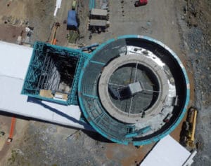
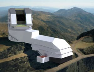
The Large Synoptic Survey Telescope (LSST) under construction atop the 8,737-foot El Peñón peak in northern Chile, is a partnership project of the National Science Foundation (NSF) and the Department of Energy (DOE).
The goal of the LSST, scheduled to be fully operational in 2022, is to conduct a 10-year survey that will deliver a 200-petabyte set of images and data addressing some of the most pressing questions about the structure and evolution of the universe and the objects within it.
The LSST will conduct a deep survey over an enormous area of sky and do it with a frequency that enables images of every part of the visible sky to be obtained every few nights. This mode will continue for 10 years to achieve astronomical catalogs thousands of times larger than have been previously compiled.
The LSST, when completed, will be the world’s most powerful survey telescope. It is a wide-field survey reflecting telescope, with an 8.4-meter primary mirror. It is unique among large telescopes because of its very wide field of view of 3.5 degrees, covering a 64-cm-diameter flat focal plane. It uses a novel three-mirror design that delivers sharp images feeding a 3.2-gigapixel CCD imaging camera — the largest digital camera ever constructed.
The camera will take a 15-second exposure of the night sky every 20 seconds — 800 panoramic images every night. That is equivalent to taking roughly 800,000 images with an eight-megapixel digital camera, but of much higher quality — more than 200,000 exposures per year of raw image data. In a 10-year survey, the LSST will produce a deep, time-dependent, multi-color movie of the sky.
Initial computer requirements are estimated at 100 teraflops of computing power (one teraflop is a measure of computing speed equivalent to one trillion floating point operations per second). The camera contains more than three billion pixels of solid-state detectors. More than 30 terabytes of data must be processed and stored each night in producing the largest non-proprietary data set in the world.
By digitally imaging the sky for a decade, the LSST will produce a petabyte-scale database enabling new paradigms of knowledge to address the most pressing questions in astronomy and physics that are driving advances in big data science and computing.
DESIGN LIMITATIONS FOR A MIRROR LIFT SYSTEM
Modern optical and infrared astronomical telescopes generally utilize large mirrors that require periodic re-coating of their reflective surfaces to maintain the high-resolution imaging demanded by their scientific missions. The need to re-coat these large mirrors requires stripping off the old coating and placing them in specialized coating chambers, generally located away from the telescope due to their size and utility requirements.

Adding to the design challenge, the mirror transporting method would be required to operate within a seismically active zone, safely absorbing seismic loads of up to 8.0 on the Richter scale, as well as resist 100-mph wind loads present on the mountaintop. Further, because the site’s elevation is at 8,737 feet above sea level, the system would need to be factory pre-constructed and tested, disassembled for shipping within containers, and reassembled onsite at the LSST facility.
ENGINEERING CHALLENGE
The use of a vertical reciprocating conveyor (VRC) was identified as a likely viable option for the LSST mirror transporting system, although there were no known precedents for using a VRC to transfer large telescope mirrors. In 2010, LSST engaged PFlow Industries, which offers complete vertical lifting solutions, to conduct an engineering analysis for the design of a VRC solution for the lift.

The PFlow solution envisioned was a permanently installed lift outside of the telescope dome enclosure, but integrated within the building structure itself that would rise up to the level of the dome and receive the payload of the mirror assembly through a back entry door. During normal telescope observing operation, all elements of the LSST lift and shaft would need to retract below the dome to stay out of the way of its rotation and out of the observing field of view of the telescope. This meant that the lift would need to raise the shaft roof when deployed to its upper position to receive the mirror from the telescope and deliver it back after recoating. The 80-foot-high lift would also need to be extremely reliable and flexibly designed to transport other large loads to various levels of the observatory facilities.
“During the design process, PFlow engineers worked closely with the LSST team,” said Mark Webster, Vice President of Engineering at PFlow. “We began with a set of approximate static equivalent loads based on the initial seismic and wind parameters, and designed an initial structural bracing scheme using finite element analysis (FEA) that would adequately support the lift during seismic and wind events. This information was shared with the Chilean engineering team along with SolidWorks models of the lift structure. After nine months of design review meetings, ongoing analysis, and exchange of structural analysis results, a final collaborative FEA model of the combined building and lift structure was created, and final structural modifications made based on the results.”
INNOVATIVE LIFT DESIGN
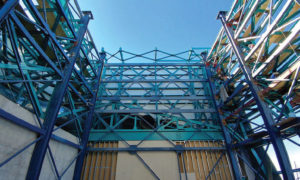
PFlow engineers leveraged and extended existing well-proven industrial technology for this new specialized application. Many features have been incorporated to protect the mirror assembly during transport, and all critical lifting components have redundancy to minimize the chance of a catastrophic failure. Key specifications and innovative features were designed into the LSST mirror assembly lift.
The entire LSST lift system incorporates approximately 160,000 pounds of fabricated steel.

The lifting system was designed such that the failure of any single lift system component would not result in a loss of control of the load. Twelve lifting chains, powered by a pair of 60-HP gear drives weighing 6,500 pounds each, are incorporated with a combined tensile strength of 974 tons.
“Roller chain drives inherently have some vibration due to the chordal action of the chain as it is driven by the sprocket,” added Webster. “The normal velocity of a lifting platform driven by a roller chain drive is not linear, but sinusoidal. A new chain drive arrangement (patent-pending) was engineered to eliminate this chordal action, resulting in a linear carriage velocity and ensuring smooth platform velocity.”
Two redundant motor/gear-reducer/ brake assemblies are provided and synchronized via shafts and couplings. Although the two motors and reducers share the load during normal operation, a single brake has adequate torque to support the entire load independent from the other.
The lift platform needed to be locked at each level to allow for the smooth transfer of the mirror aboard a wheeled cart riding on rails. Alignment of the rails was critical, and any motion of the platform needed to be eliminated. The Pflow solution was to provide carriage-mounted powered locks that automatically extend when the platform is at any floor level. “The control system automatically extends the locks and smoothly sets the platform onto the locks, relieving the tension from the lifting chains,” continued Webster. “To accomplish this smoothly, a variable frequency drive is employed that slows the travel velocity to a low speed to minimize the impact when setting down onto the locks.”
A guide system, located near the bottom of the carriage structure, allows the carriage to extend above guide columns and lift the 20,000-pound observatory roof section 15 feet vertically.
Due to the potential for seismic and wind events, the moveable roof section is mechanically locked to the building structure when in the normal lowered position. When the lift platform is raised to the roof level, another set of mechanical locks attaches the roof to the specially designed lifting structure at the top of the lifting carriage. It is important that the roof section is never left unlatched and unprotected from the potential of wind damage. A special lock system was developed that locks the roof section to the lifting carriage structure prior to unlatching the roof from the building structure. Only after signals are exchanged verifying that the platform locks are engaged are the building locks allowed to disengage and the roof raised.
LSST CONSTRUCTION PROJECT
The LSST construction project is funded by the NSF and the DOE. The NSF supports construction of the telescope and site facility, data management system, and education and public outreach components of LSST, as well as the project management and system engineering efforts. DOE is providing the camera and related instrumentation. Both agencies expect to support post-construction operation of the observatory. Site and facility design, engineering, and construction are under the direction of, and managed by, the LSST architectural and design team, working in affiliation with an onsite Chilean engineering group.
As early as 2005, construction of the telescope’s 8.4-meter-diameter primary mirror — the most critical and time-consuming part of a large telescope’s construction — was underway at the University of Arizona’s Richard F. Caris Mirror Lab. The following year, the site for the LSST telescope was selected at the El Peñón peak alongside the existing Gemini South telescope and Southern Astrophysical Research telescopes. The site is inland and approximately 60 miles by road from the support town of La Serena, where the LSST base facility is located.
Site excavation began in March 2011, followed by start of construction of the telescope facility in January 2015. By 2018, the facility was substantially completed. The vertical reciprocating conveyor is in the process of being fully completed and tested.
Science first light is anticipated in 2021, and full operations for a 10-year survey commences in January 2022.
